The satellite communications industry is experiencing a significant migration toward higher frequencies. As traditional C-band and Ku-band spectrum becomes increasingly congested, operators are turning to millimeter-wave bands to meet growing capacity demands. This transition brings substantial technical challenges, particularly in the design and selection of waveguide components that must perform reliably at frequencies where every fraction of a decibel matters.
Millimeter-wave frequencies, generally defined as those above 30 GHz, offer tremendous bandwidth potential but impose stringent requirements on RF hardware. The physics of electromagnetic propagation at these frequencies leaves little margin for error. Surface roughness that would be imperceptible at lower frequencies causes measurable losses. Dimensional tolerances that seem unnecessarily tight become essential for proper operation. Manufacturing techniques adequate for conventional waveguide prove insufficient when wavelengths shrink to mere millimeters.
For system designers and procurement engineers, understanding these challenges is essential for making informed component selections. The waveguide assembly that performs beautifully in a laboratory demonstration may fail when deployed in a real satellite ground station, exposed to temperature extremes, mechanical stresses, and years of continuous operation. Conversely, over-specifying components drives unnecessary costs without improving system performance.
This guide examines the key considerations for selecting waveguide components in millimeter-wave satellite applications, from fundamental technology choices through manufacturing requirements and qualification testing.
Millimeter-wave frequency advantages
The push toward millimeter-wave frequencies reflects fundamental capacity limitations at traditional satellite bands. Spectrum availability at Q-band (33-50 GHz) and V-band (40-75 GHz) dwarfs what remains at lower frequencies, enabling dramatically higher data throughputs for both gateway links and user terminals.
Bandwidth allocations at Q-band and V-band typically span several gigahertz, compared to hundreds of megahertz at Ku-band. This expanded spectrum directly translates to increased capacity, allowing a single ground station to support throughputs that would require multiple antennas at conventional frequencies. For high-throughput satellite systems designed to deliver broadband connectivity, this capacity multiplication proves economically decisive.
Antenna gain increases proportionally with frequency for a given aperture size. A one-meter dish operating at V-band achieves the same gain as a much larger antenna at Ku-band. This relationship enables more compact ground terminals without sacrificing link performance, opening new deployment possibilities where space constraints previously precluded satellite connectivity.
Interference characteristics also favor millimeter-wave operation. Higher atmospheric attenuation, often cited as a disadvantage, actually reduces interference between adjacent satellite systems and terrestrial networks. The same rain fade that challenges link availability also provides natural frequency reuse, allowing more aggressive orbital slot utilization.
However, these advantages come with significant implementation challenges. Atmospheric absorption increases substantially above 30 GHz, with particularly severe effects near water vapor and oxygen resonance lines. Link budgets must accommodate rain fade margins that can exceed 20 dB in tropical regions. And critically, RF component performance requirements tighten dramatically as operating frequencies increase.
Waveguide technology overview
At millimeter-wave frequencies, waveguide remains the transmission medium of choice for high-performance systems. While coaxial cables and printed transmission lines offer convenience at lower frequencies, their losses become prohibitive as wavelengths shrink. Waveguide, with its enclosed metallic boundaries and air dielectric, provides the lowest possible attenuation for a given frequency band.
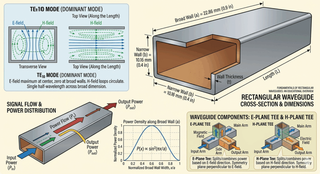
The fundamental principle involves electromagnetic waves propagating through a hollow metallic tube, typically rectangular in cross-section for satellite communications applications. The waveguide dimensions determine the frequency range over which proper operation occurs, with standardized sizes established for each band.
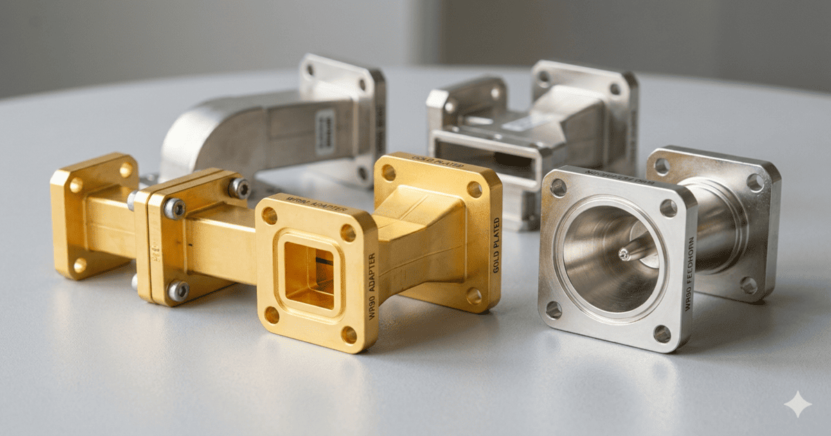
Rectangular waveguide dominates millimeter-wave satellite applications. Standard designations like WR-22 (Q-band) and WR-15 (V-band) specify precise internal dimensions that ensure compatibility between components from different manufacturers. These standards prove essential for system integration, allowing designers to combine feedhorns, transitions, filters, and other components into complete assemblies.
Circular waveguide finds application in specific scenarios, particularly for antenna feeds where rotational symmetry simplifies polarization handling. Transitions between rectangular and circular sections add complexity but enable optimized performance where each geometry offers distinct advantages.
The choice of waveguide material significantly impacts both performance and cost. Aluminum provides an economical baseline with adequate conductivity for many applications. Brass offers improved dimensional stability and solderability. Silver-plated surfaces maximize conductivity, reducing losses at the expense of increased material and processing costs. For the most demanding applications, gold plating provides oxidation resistance that maintains performance over extended operational lifetimes.
Component selection guide
Successful millimeter-wave system design requires careful selection of each waveguide component. Understanding the critical parameters and their interactions helps engineers balance performance requirements against practical constraints.
Q/V-Band specifications
Q-band waveguide components typically operate across the 33-50 GHz range, using WR-22 or WR-19 standard waveguide sizes. Key specifications include insertion loss below 0.05 dB per transition, return loss exceeding 25 dB, and power handling appropriate for the intended application.
V-band components face even tighter requirements. Operating frequencies between 40-75 GHz demand WR-15 or WR-12 waveguide, with correspondingly smaller physical dimensions. Manufacturing tolerances that represent acceptable fractions of a wavelength at Q-band become unacceptably large at V-band frequencies.
Designers must specify the exact frequency range required, as components optimized for different portions of these bands may not be interchangeable. A feedhorn designed for the 47.2-50.2 GHz gateway downlink band may not perform acceptably in the 42.5-43.5 GHz uplink allocation, despite both falling within the general V-band designation.
Insertion loss minimization
Insertion loss represents the primary performance concern at millimeter-wave frequencies. Every component in the signal path contributes loss, and these contributions accumulate quickly in complex assemblies. A ground station RF chain might include feedhorn, polarizer, orthomode transducer, multiple transitions, and interconnecting waveguide runs, each adding fractions of a decibel that collectively impact system noise figure and transmit efficiency.
Component manufacturers employ various techniques to minimize insertion loss. Surface finish quality directly impacts conductor losses, driving requirements for polishing and plating processes that would be unnecessary at lower frequencies. Joint design between mating components affects both loss and repeatability, with precision flanges and careful alignment provisions becoming essential.
Waveguide transitions deserve particular attention. These components convert between different waveguide sizes, transmission line types, or propagation modes. Poorly designed transitions introduce significant losses and reflections that cascade through subsequent system elements. Quality transitions employ gradual tapers and carefully shaped discontinuities that minimize mode conversion and maintain smooth impedance profiles.
Power handling at mmWave
Power handling capability becomes increasingly complex at millimeter-wave frequencies. While coaxial connectors at lower frequencies fail primarily through dielectric breakdown, waveguide power limits involve multiple mechanisms that interact in subtle ways.
Voltage breakdown in air-filled waveguide establishes ultimate power limits. The peak electric field intensity varies with waveguide mode and dimensions, creating design tradeoffs between power handling and other performance parameters. Pressurization with dry air or nitrogen raises breakdown thresholds, enabling higher power operation where necessary.
Thermal management often proves more limiting than electrical breakdown for continuous-wave applications. Conductor losses generate heat that must dissipate through the waveguide walls. Inadequate thermal design leads to temperature rises that affect dimensional stability, material properties, and ultimately component lifetime.
Multipaction, the resonant acceleration of free electrons between waveguide surfaces, creates particular challenges for space-qualified hardware operating in vacuum. Surface treatments and geometric modifications suppress multipaction, but at cost penalties that must be balanced against mission requirements.
Manufacturing precision requirements
The diminutive wavelengths at millimeter-wave frequencies impose extraordinary demands on manufacturing precision. A dimensional error of 0.1 mm, negligible in a C-band component, represents a significant fraction of a wavelength at V-band and noticeably degrades performance.
Environmental considerations
Thermal stability requirements intensify at millimeter-wave frequencies. Aluminum waveguide expands approximately 23 parts per million per degree Celsius. For a precision V-band component, temperature excursions of even 20°C produce dimensional changes comparable to manufacturing tolerances.
System designers must consider the full environmental envelope. Ground station equipment in temperate climates may experience annual temperature variations of 50°C or more. Satellite-borne hardware faces even greater extremes, from pre-launch storage through orbital thermal cycling. Components must maintain specifications across this entire range, not merely at room temperature calibration conditions.
Moisture and contamination pose additional concerns. Water absorption in dielectric materials alters electrical properties, while surface contamination increases conductor losses. Appropriate sealing, desiccation, and handling procedures protect component performance throughout operational lifetimes.
Manufacturers like Celestia-TTI address these challenges through precision CNC machining, carefully controlled plating processes, and comprehensive environmental testing programs that validate performance across expected operating conditions.
Testing and qualification
Performance verification at millimeter-wave frequencies requires sophisticated measurement capabilities. Network analyzers must cover the frequency ranges of interest with adequate dynamic range to measure low insertion losses accurately. Calibration standards traceable to national metrology institutes ensure measurement validity.
Environmental qualification demonstrates component survival and performance across operational conditions. Thermal cycling tests verify dimensional stability. Vibration and shock testing confirms mechanical integrity through launch loads. Humidity exposure validates sealing effectiveness.
For space applications, additional qualification requirements apply. Multipaction testing verifies power handling in vacuum conditions. Outgassing measurements ensure materials compatibility with sensitive spacecraft surfaces. Radiation testing confirms immunity to orbital environment effects.
Documentation requirements for qualified passive RF components typically include full dimensional inspection reports, material certifications, test data across environmental conditions, and traceability records linking specific units to qualified manufacturing processes.
Future applications
The millimeter-wave transition continues accelerating, driven by insatiable demand for satellite capacity and enabling technology improvements. Several emerging applications promise to expand waveguide component markets significantly.
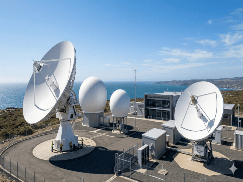
High-throughput satellite gateways increasingly operate at Q-band and V-band, concentrating enormous data volumes through individual ground stations. These installations require the highest-performance waveguide assemblies available, with every component optimized for minimum loss and maximum reliability.
LEO constellation feeder links bring new requirements for compact, cost-effective millimeter-wave hardware. Where traditional geostationary systems might deploy dozens of gateway terminals, LEO constellations may require hundreds or thousands. Manufacturing scalability and cost optimization become essential alongside raw performance.
5G backhaul applications extend millimeter-wave satellite connectivity to terrestrial networks. Integration with cellular infrastructure demands components that meet telecommunications industry reliability expectations while maintaining RF performance at frequencies unfamiliar to many traditional suppliers.
Inter-satellite links at millimeter-wave frequencies enable mesh connectivity among constellation spacecraft. These links impose unique requirements combining high performance with space qualification, creating opportunities for manufacturers capable of meeting both demands simultaneously.
Waveguide component selection for millimeter-wave satellite systems demands careful attention to specifications, manufacturing quality, and environmental performance. The forgiving margins available at lower frequencies disappear as operating frequencies increase, making every design choice consequential.
Engineers approaching millimeter-wave projects should establish clear performance requirements early, considering not just nominal specifications but environmental variations and long-term reliability needs. Component suppliers should be evaluated not merely on datasheet parameters but on demonstrated manufacturing capability, quality systems, and relevant application experience.
The investment in proper component selection pays dividends throughout system lifetime. A well-designed millimeter-wave RF assembly delivers consistent performance year after year, while marginal components create ongoing operational challenges that far exceed their initial cost savings.
As satellite communications continues its migration toward higher frequencies, expertise in millimeter-wave waveguide technology becomes increasingly valuable. Organizations building this expertise today position themselves advantageously for the expanded millimeter-wave deployments certain to follow.